
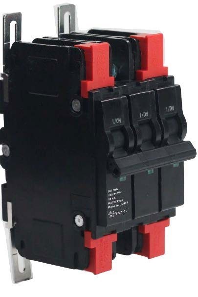
The numbers you need with the cover off
Everything below comes from the Legacy Shield™ LS A1U-60 Component Datasheet v1.0. Apply within nameplate ratings only.
- Rated current
- 5–60 A11 ratings per pole configuration
- Rated voltage
- 120/240 VVAC · 50/60 Hz · 3-pole 240 VAC
- Interrupting rating
- 10 kAIcu = Ics = 10 kA
- Trip curve
- Type CThermal-magnetic · instantaneous 6.4–9.6 In
- Conductors
- 14–4 AWGCopper only · 60/75 °C · 2–25 mm²
- Terminal torque
- 3.5 N·m31 lb·in — verify every terminal
Build the catalog number
Pick the rating, the poles and any accessories. The catalog number, part numbers and ratings update from the ordering tables in the datasheet.
Pricing and volume quotes through Legacy Controls or your local authorized Legacy Controls sales and service provider.
Specifications
UL 489 listed, thermal-magnetic, suitable for main or branch circuit protection in industrial control panels, power supply equipment, HVAC systems and lighting and receptacle circuits.
- Applicable standard
- UL 489
- Rated current
- 5 – 60 A
- Rated voltage
- 120/240 VAC (1 & 2 pole) · 240 VAC (3 pole)
- Rated frequency
- 50/60 Hz
- Rated insulation voltage
- 1,000 VAC
- Rated impulse withstand
- 6 kV
- Tripping type
- Thermal magnetic
- Tripping characteristic
- Type C (6.4 In – 9.6 In)
- Short-circuit current (Icu)
- 10 kA
- Operating breaking capacity (Ics)
- 10 kA
- Protection degree
- IP20
- Electrical life
- 6,000 operations
- Mechanical life
- 10,000 operations
- Operating temperature
- −25 °C to +40 °C (reference 30 °C)
- Pollution level
- Class III
- Elevation
- Not exceeding 6,561 ft (2,000 m)
- Relative humidity
- ≤ 90 % at 20 °C · ≤ 50 % at 40 °C
- Conducting wire
- 14 – 4 AWG (2 – 25 mm²) copper
- Conductor temperature
- 60/75 °C
- Terminal torque
- 3.5 N·m (31 lb·in)
- Installation
- 35 mm DIN rail · optional feet for bottom or surface mounting
UL interrupting rating
| Circuit breaker type | Poles | Ampere rating | 120/240 VAC | 240 VAC |
|---|---|---|---|---|
| LS A1U-60 | 1 | 5 – 60 A | 10 kA | N/A |
| LS A1U-60 | 2 | 5 – 60 A | 10 kA | N/A |
| LS A1U-60 | 3 | 5 – 60 A | N/A | 10 kA |
Type C trip curve
Type C thermal-magnetic trip element with an instantaneous trip region of 6.4–9.6 In (8 In ± 20 %).
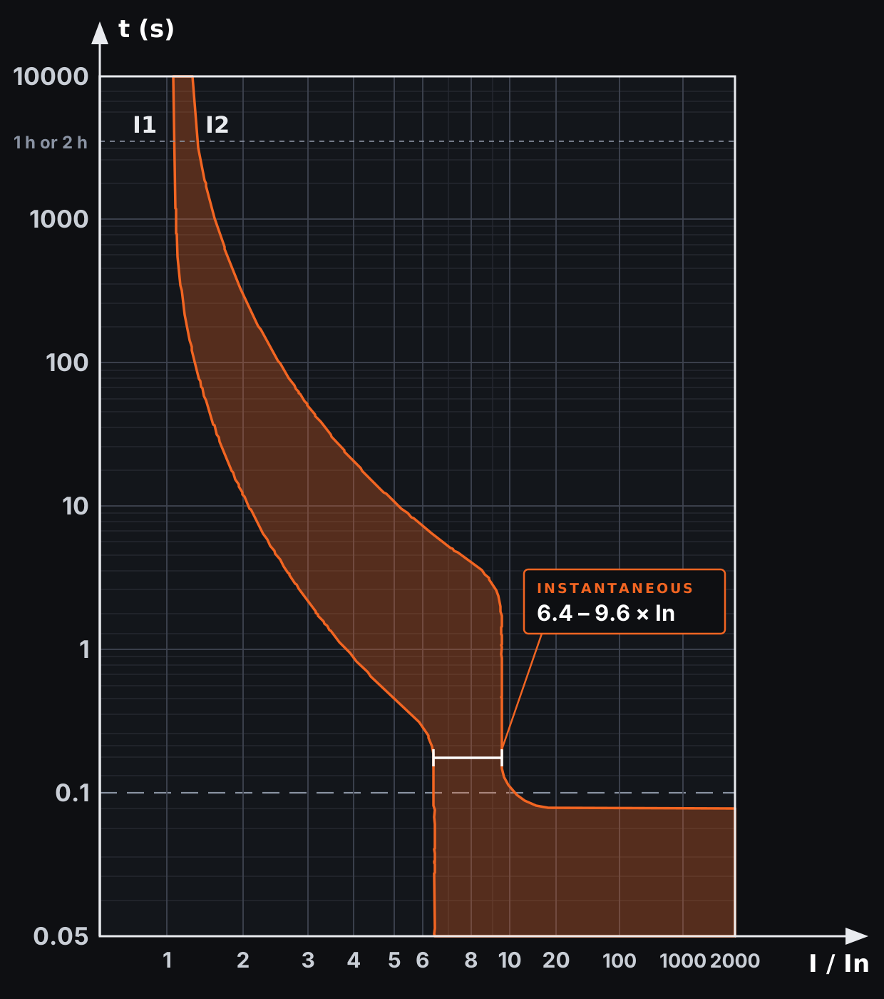
No trip for t > 1 h (In ≤ 50 A) · t > 2 h (In > 50 A).
Trips within t ≤ 1 h (In ≤ 50 A) · t ≤ 2 h (In > 50 A).
Type C magnetic trip band — 8 In ± 20 %.
Dimensions
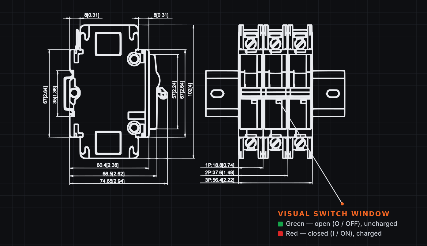
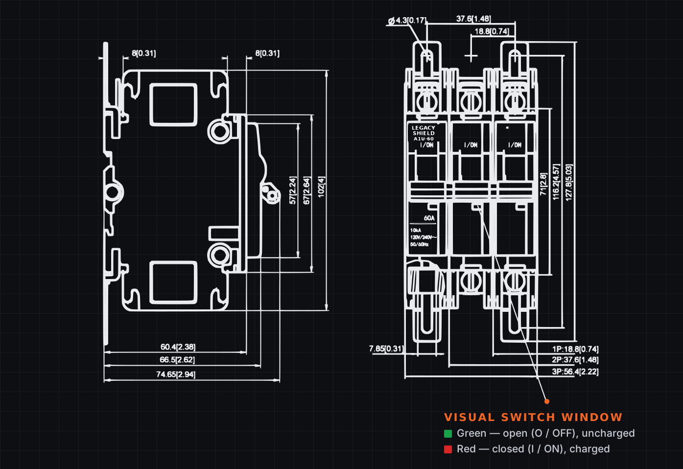
All dimensions mm [inch]. The visual switch window shows green when open (O / OFF) and red when closed (I / ON).
Pole width
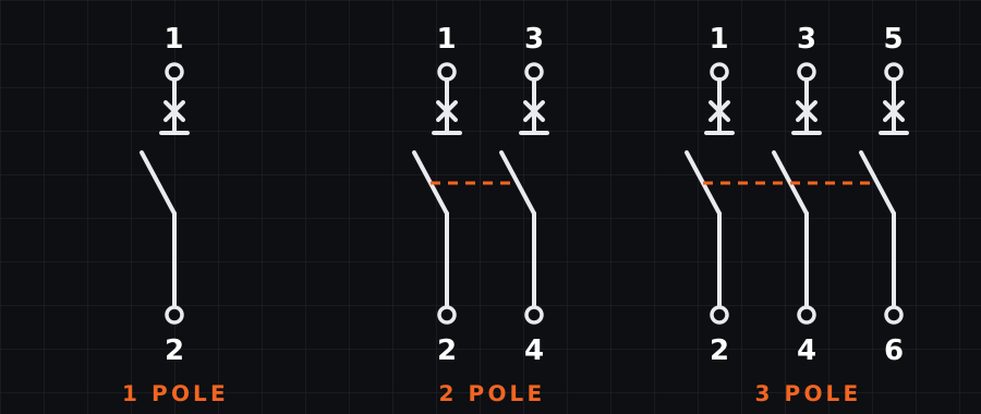
- 1 Pole18.8mm · 0.74 in
- 2 Pole37.6mm · 1.48 in
- 3 Pole56.4mm · 2.22 in
Product weight
- 1 Pole0.161kg · 5.7 oz
- 2 Pole0.314kg · 11.1 oz
- 3 Pole0.467kg · 16.5 oz
Install it right
Risk of electric shock and serious injury. Installation must be carried out by qualified personnel only, per the National Electrical Code (NEC) and all applicable local codes. De-energize the circuit and verify with a voltage tester before installing or servicing any breaker.
- Conductors
Copper wire only, 14–4 AWG (2–25 mm²), temperature rating 60/75 °C.
- Terminal torque
Tighten terminals to 3.5 N·m (31 lb·in) and verify all torque values. Reliable connections prevent terminal overheating and burn-out.
- Mounting
Standard 35 mm DIN rail; optional mounting feet (MF) enable bottom or surface mounting.
- Multi-pole operation
Operate 2- and 3-pole handles from the center position. Normal ON/OFF switching time is less than 1 second.
- Locking
The handle is lockable in the ON or OFF position; the HS handle safety lock secures either position.
Backed by the people who build it
Limited warranty
24 months
Legacy Shield™ Series circuit breakers are warranted for twenty-four (24) months from the date of purchase against defects in materials and workmanship. Legacy Controls will repair or replace, at its sole discretion, any defective unit returned with proof of purchase, provided it was used under normal operating conditions.
Warranty void if
- Products are misused, altered, or improperly installed.
- Damage results from accidents, overload, or environmental factors.
- The unit is repaired by unauthorized personnel.
Making a claim
Contact Legacy Controls within the warranty period with proof of original purchase, the catalog number, and a detailed description of the issue. If directed, return the unit to the designated Florida facility, shipping prepaid.
Technical support, ordering & warranty claims
Legacy Controls · 6200 FL-46, Mims, Florida 32754
Compliance & notes
- Installation by qualified personnel only, per NEC and all applicable local codes.
- Suitable for main or branch circuit protection when applied within nameplate ratings.
- Copper conductors only, 14–4 AWG, 60/75 °C · terminal torque 3.5 N·m (31 lb·in).
- Any alteration, modification, or unauthorized repair voids the UL listing and warranty.